
Views: 0 Author: Site Editor Publish Time: 2026-07-26 Origin: Site


Bridging large spans efficiently challenges commercial and industrial construction teams daily. Engineers must cross massive interior gaps without compromising load-bearing capacity or inflating material costs needlessly. Solid beams often become too heavy over long distances, creating immense pressure on building foundation systems. The steel truss solves this architectural dilemma beautifully. It acts as a standardized, mathematically proven framework designed to distribute immense weight seamlessly. By converting bending moments into pure tension and compression, it maximizes structural efficiency and reduces total tonnage.
This article moves beyond basic engineering definitions to explore real-world applications. We provide a comprehensive structural evaluation framework for architects, engineers, and project developers. You will discover the core mechanics driving these systems and explore primary configurations used across multiple heavy industries. We also cover compliance standards, fabrication logistics, and erection realities. These insights will help you select the ideal structural solution for your upcoming commercial development projects.
Steel truss structures distribute loads through a network of triangles, drastically reducing material weight while maintaining high structural rigidity.
Selecting between Pratt, Warren, and Howe configurations depends heavily on specific span requirements, load types (static vs. dynamic), and architectural constraints.
Compliance with established engineering standards (e.g., AISC or local equivalents) is mandatory for safety and project viability.
Total cost evaluation must factor in transportation logistics, site erection complexity, and required fireproofing or anti-corrosion treatments, not just raw material pricing.
Engineers define a steel truss as a planar or spatial framework. It consists of straight structural members connected at specific joints called nodes. These nodes play a crucial role in maintaining overall structural integrity. Heavy steel gusset plates often reinforce these connection points. They ensure the geometric centroid of each member aligns perfectly at the joint. This precise alignment prevents eccentric loading from destabilizing the frame.
External forces push and pull constantly on the building envelope. The nodes transfer these external loads directly into axial forces along the members. Each individual beam experiences either pure tension or pure compression. They do not experience bending moments. This fundamental force distribution prevents individual steel components from bowing or snapping under massive roof weights.
Nodal force distribution creates incredible material efficiency. Solid steel components, like traditional I-beams or H-beams, carry excess dead weight in their web sections. A triangulated framework relies on calculated empty space and strategic geometry instead. Triangles form the absolute core of this geometric efficiency. They naturally lock the structure in place, offering a superior strength-to-weight ratio. This ratio allows builders to span massive distances while utilizing far less raw steel tonnage.
Different architectural challenges demand highly specific structural configurations. You must match the framework geometry carefully to your project load demands. Selecting the wrong profile can lead to material waste or structural failure.
Pratt configurations feature vertical members under compression and diagonal members under tension. We often see them utilized heavily in commercial flat-roof buildings and pedestrian footbridges. They offer highly cost-effective solutions for moderate clear spans reaching up to 250 feet. Using tension for the longest diagonal members reduces sudden buckling risks significantly. This makes the Pratt design highly reliable for static roof loads.
Warren designs utilize a continuous series of equilateral triangles. The diagonal members alternate constantly between tension and compression states. This specific layout excels at supporting heavy, distributed loads evenly across the entire span. Industrial warehousing facilities, crane-bearing structures, and vehicular bridges frequently deploy Warren configurations. They provide exceptional structural rigidity while minimizing unnecessary material usage.
Howe structures function geometrically as the exact opposite of Pratt designs. Their diagonal members face compression while the vertical members experience tension. This specific geometry makes them ideal for industrial scenarios involving heavy centralized loads. They also perform exceptionally well for specific architectural pitched-roof requirements, common in agricultural or storage facilities.
These configurations represent specialized architectural niche use cases. Scissor designs angle upward sharply from the bottom chord. They maximize vaulted ceiling clearances inside luxury commercial buildings or churches. Bowstring designs utilize a curved, arched top chord for specialized weight distribution. Aviation hangars, indoor sports arenas, and large exhibition halls rely heavily on these arched frameworks to manage extreme roof spans.
Analyze the primary wind and snow load direction before choosing a structural profile.
Match the geometric bottom chord profile to your required architectural ceiling height.
Consult advanced analysis models to verify critical stress points early in the design phase.
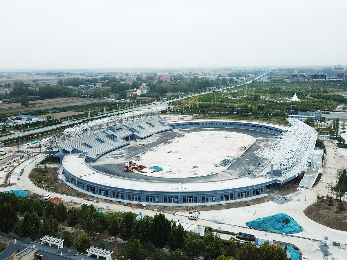
Space optimization drives modern commercial construction decisions globally. Specifying a triangulated framework unlocks significant operational advantages for ambitious facility developers.
You can cover massive factory floor areas without relying on internal supporting columns. This scalability maximizes usable square footage inside complex industrial facilities. Removing interior columns improves workflow efficiency drastically in manufacturing plants and automated distribution centers. Forklifts and heavy machinery navigate open floor plans much safer without navigating around structural pillars.
Structural metal offers inherent material properties traditional timber simply cannot match. It boasts exceptionally high tensile strength and complete resistance to biological rot or pest infestations. Environmental degradation affects wood rapidly over time, especially in humid climates. Metal frameworks maintain their predictable durability and load capacity across decades of heavy industrial use.
Modern commercial buildings require complex mechanical, electrical, and plumbing networks. The open-web design of these frameworks naturally accommodates routing for massive HVAC ducts and heavy electrical conduits. Plumbers and electricians can run utilities directly through the structural voids. This layout reduces drop-ceiling requirements and saves highly valuable vertical building space.
Transparently, metal frameworks present specific limitations in highly volatile environments. Extreme heat compromises bare structural integrity very quickly. Projects require mandatory investments in advanced fireproofing, such as spray-on intumescent coatings. Corrosive coastal environments also demand robust protection strategies. Hot-dip galvanizing or applying specialized industrial epoxies prevents rust degradation and extends the building lifespan.
Public safety relies entirely on rigorous mathematical validation. Engineering these structures requires absolute adherence to established international building protocols.
You must engineer every framework to meet rigorous industry standards meticulously. Organizations like the American Institute of Steel Construction (AISC) dictate strict design parameters. European projects follow comprehensive Eurocode 3 regulations closely. Engineers choose between Allowable Strength Design (ASD) or Load and Resistance Factor Design (LRFD) methodologies. Code adherence remains mandatory for public safety and legal project viability.
Engineers perform mandatory mathematical load assessments long before factory manufacturing begins. They categorize these calculations into three primary groups to ensure structural redundancy.
Dead Loads: The permanent, static weight of roofing materials, decking, and fixed building components.
Live Loads: Temporary environmental forces including heavy snow accumulation, severe wind pressure, and sudden seismic activity.
Collateral Loads: Suspended interior weights like heavy mechanical equipment, lighting grids, and commercial sprinkler systems.
Advanced structural software verifies modern building applications before a single piece of metal gets cut. Engineers utilize finite element analysis (FEA) to model complex stress points visually. They simulate extreme weather events digitally to observe how the framework reacts. This digital twin approach ensures total code compliance prior to physical fabrication. It eliminates dangerous guesswork and prevents catastrophic structural failures.
Load Category | Definition | Common Construction Examples |
|---|---|---|
Dead Load | Static weight of permanent structural elements. | Roof decking, metal members, permanent architectural fixtures. |
Live Load | Transient forces applied by environment or dynamic usage. | Snow accumulation, wind pressure, maintenance foot traffic. |
Collateral Load | Additional suspended utility and equipment weight. | Rooftop HVAC units, plumbing pipes, electrical cable trays. |
Translating digital architectural designs into physical buildings introduces complex logistical challenges. Construction managers must navigate factory fabrication, cross-country shipping, and dangerous installation hurdles carefully.
Factory pre-fabrication offers immense quality control advantages for developers. Indoor climate-controlled environments allow for exact manufacturing tolerances and certified automated welding procedures. However, highway shipping constraints severely limit the maximum physical size of factory-built units. On-site assembly solves these size limitations effectively. It allows for massive spans but introduces severe weather dependencies and higher field-welding risks.
Moving oversized structural components to the rural or urban job site requires meticulous logistical planning. You often need specialized state highway permits and multiple escort vehicles. Modular delivery schedules must align perfectly with exact site readiness. Arriving too early clutters the dangerous workspace. Arriving too late stalls the entire construction timeline and inflates labor costs.
Installing massive metal components demands specialized heavy lifting equipment. Heavy-duty crawler cranes hoist the awkward sections into place carefully. Workers must install temporary steel bracing immediately during the initial installation phase. This temporary bracing prevents sudden lateral collapse before the roof deck goes on. Project teams must also choose between on-site structural bolting or field welding. Bolting accelerates the installation speed significantly. Field welding provides seamless aesthetic joints but requires highly paid, skilled labor.
Failing to stage delivery trucks in the correct sequential unloading order.
Removing temporary cable bracing before securing the permanent secondary framing entirely.
Overlooking soft ground soil conditions before positioning heavy crane equipment.
Choosing the right fabrication partner determines your ultimate project success. You must evaluate potential manufacturing partners far beyond their initial quote.
Shortlisting reliable partners requires a close look at their operational factory facilities. Seek out fabricators heavily equipped with precision CNC cutting and drilling machinery. Verify they employ certified welding inspectors (CWIs) directly on the factory floor for quality assurance. You must also confirm their monthly tonnage production capacity aligns with your aggressive project timeline.
Prudent buyers should always require detailed shop drawings before ever approving mass production. Demand official connection design stamps from licensed third-party structural engineers. Request raw material mill certificates to verify metal origin and chemical composition accuracy. These critical submittals guarantee the physical materials match your specified engineering grades exactly.
Smart project managers look past the raw material pricing alone. They evaluate the entire manufacturing and installation process holistically. Factoring in guaranteed delivery timelines and site erection ease provides a much clearer picture of actual project expenditures. A slightly higher initial fabrication cost often saves thousands in reduced crane rental time. Precise factory manufacturing also eliminates costly on-site modifications and accelerates field assembly.
The right structural framework seamlessly aligns complex load-bearing mathematics with project-specific spatial constraints. It delivers massive open floor plans without inflating foundation requirements unnecessarily. Your final purchasing decision matrix must balance three equal pillars for a successful rollout. Configuration geometry, strict code compliance, and precise factory fabrication quality matter equally.
We encourage project managers and commercial engineers to take the next step proactively. Do not leave your structural integrity to chance. Submit your architectural drawings and environmental load requirements to a certified manufacturer today. An expert structural review will identify potential design efficiencies immediately. This professional evaluation provides a realistic, optimized preliminary quote to keep your development on track and under budget.
A: Standard commercial designs typically span between 40 to 100 meters. This depends heavily on the specific geometric configuration and local environmental load requirements. However, custom engineering pushes these limits significantly further. Advanced materials and specialized arched profiles allow professional stadiums and aviation hangars to achieve massive clear spans well beyond standard commercial limitations.
A: Steel joists act as smaller-scale, highly standardized components. Builders use them primarily for basic floor or roof support at closely spaced intervals. Conversely, large-scale frameworks undergo intensive custom engineering for major clear spans. They serve as the primary load-carrying backbone of the entire building, whereas joists typically act merely as secondary framing elements.
A: A distinct structural breakeven point exists. Fabricating complex geometric networks costs more in specialized labor and factory time than rolling solid I-beams. However, over long spans, they save significantly on total raw material weight and deep foundation concrete costs. The overall project expenditure often decreases noticeably when spanning distances exceeding 60 feet.
A: Realistic industry timeframes usually range from 8 to 16 weeks. This timeline accounts for initial engineering design approvals, raw material procurement, and current factory production queues. Complex architectural designs or specialized protective marine coatings can extend lead times further. Early engagement with a certified fabricator remains crucial for meeting tight construction schedules.


