
Views: 0 Author: Site Editor Publish Time: 2026-07-23 Origin: Site


Facility planners and builders consistently face a critical design challenge. You need to maximize unobstructed floor space for efficient day-to-day operations. Achieving a massive clear span offers ultimate operational flexibility, but pushing these boundaries can quickly trigger exponential project price increases. Steel undeniably offers a superior strength-to-weight ratio compared to traditional timber framing. However, engineering extreme spans requires complex load calculations, heavier metal profiles, and highly demanding logistical planning. If you misjudge these crucial factors, you risk compromising the building envelope or facing severe delivery delays. This article provides evidence-based parameters for determining maximum structural capabilities. You will discover the specific engineering criteria dictating physical limits in modern construction. Furthermore, we will help you pinpoint the exact threshold where adding interior columns becomes a smarter financial and structural decision.
Standard Cold-Formed Steel (CFS) roof trusses typically span between 40 to 80 feet without interior support.
Heavy structural steel and Pre-Engineered Building (PEB) systems can achieve clear spans of 150 to over 300 feet, though costs scale significantly.
Maximum span is never an isolated metric; it is strictly dictated by local environmental loads (snow, wind, seismic), truss spacing, and roof pitch.
Beyond certain lengths (usually 80+ feet), highway transportation logistics become a primary limiting factor, often requiring multi-piece trusses assembled on-site.
Cold-Formed Steel (CFS) remains highly popular for residential structures. It also dominates light-commercial construction projects. Builders utilize rolls of structural quality sheet steel. Manufacturers run this metal through continuous roll-forming machines. This process shapes the material into rigid C-shapes or U-shapes at room temperature. Manufacturers typically utilize 12-gauge to 16-gauge steel for these specific applications. Factory workers assemble these pieces using high-strength self-tapping screws.
These specific profiles generally reach their practical limit around 80 feet. CFS offers a remarkable strength-to-weight advantage for these moderate lengths. You can lift and maneuver them much more easily than heavy iron alternatives. They resist rot perfectly. Termites cannot destroy them. A properly engineered steel truss provides immense structural stability without overloading the concrete foundation.
Consider these primary advantages of utilizing CFS for standard spans:
Reduced structural weight lowers concrete foundation requirements.
Non-combustible materials often decrease facility insurance premiums.
High dimensional stability prevents warping and twisting over time.
Rapid manufacturing speeds up overall project timelines.
When projects demand massive scale, builders turn to heavy structural steel. Industry professionals often call this red iron. Pre-Engineered Building (PEB) systems utilize thick rigid frames. They achieve monumental clear spans ranging from 150 to well over 300 feet.
These heavy-duty structures dominate industrial warehouses. You see them heavily utilized in aviation hangars and large agricultural facilities. Achieving these extreme lengths requires exceptionally deep structural profiles. Engineers often specify massive wide-flange beams or custom-welded plate components. Manufacturers must deploy highly customized engineering to handle the immense weight.
Sports arenas and commercial airplane hangars push structural science limits. Building a 250-foot clear span requires massive plate fabrication. Welders must join thick flanges and webs to handle immense internal stresses. Every single component requires precise factory fabrication. You cannot simply cut these massive pieces on the job site. Factory precision guarantees ultimate safety across monumental distances.
System Type | Typical Max Clear Span | Primary Applications | Logistical Complexity |
|---|---|---|---|
Cold-Formed Steel (CFS) | 40 to 80 feet | Residential, Retail, Self-Storage | Low to Moderate |
Heavy Structural (Red Iron) | 150 to 300+ feet | Aviation, Arenas, Heavy Industrial | Extremely High |
Span limits never exist in a vacuum. Environmental load factors exponentially reduce achievable distances. Engineers categorize these external forces into dead loads and live loads.
Dead loads represent constant, unchanging weight. They include roofing materials like heavy standing seam metal. Dead loads also account for thick rigid insulation boards. Facility managers often suspend heavy HVAC ductwork from the bottom chords. Fire sprinkler systems add significant permanent water weight to the structure.
Live loads fluctuate based on weather events and facility usage. Heavy snow accumulation pushes straight down on the roof deck. High winds create massive upward suction. We call this uplift force. A building located in a heavy snow zone cannot span as far as one in a mild climate. You must account for these regional forces early in the design phase.
Consider the following environmental variables before designing your facility:
Snow Loads: Lake-effect snow regions require significantly thicker structural chords to prevent collapse.
Wind Speeds: Coastal hurricane zones demand enhanced cross-bracing and stronger foundation hold-downs.
Seismic Activity: Earthquake zones require specialized ductile connections to absorb lateral shocks safely.
Engineers carefully calculate deflection limits to ensure structural integrity. Standard deflection criteria often sit at L/360 or L/240. This specific ratio measures how much the structure safely bends under maximum load.
Imagine a 60-foot length utilizing an L/360 limit. The formula allows exactly two inches of maximum vertical bending at the center. A massive structure might not break across a long distance. However, excessive bowing causes immediate secondary problems.
Brittle interior finishes, like plaster or specialized drywall, crack easily under stress. Bending forces can snap mechanical fasteners holding exterior roof panels. This movement ultimately damages the critical roof envelope. Preventing water leaks requires strict adherence to deflection limits. When you push distance limits, material stiffness becomes just as important as raw strength.
You must intelligently balance spacing and pitch to optimize structural performance. Truss spacing shares a direct inverse relationship with span distance.
Wider spacing places higher individual loads onto each supporting frame. If you space frames five feet apart, each one carries significantly more roof weight. Tighter spacing, such as two feet on center, reduces individual burdens. This tighter arrangement allows you to cross further distances using the exact same profile thickness.
Roof pitch also plays a vital structural role. Steeper roof pitches inherently increase the internal depth at the peak. This added depth provides much greater internal leverage against downward forces. Consequently, steep pitched roofs allow for longer clear spans. Low-slope or flat designs lack this geometric advantage. They rely entirely on heavier, thicker metal to resist bending.
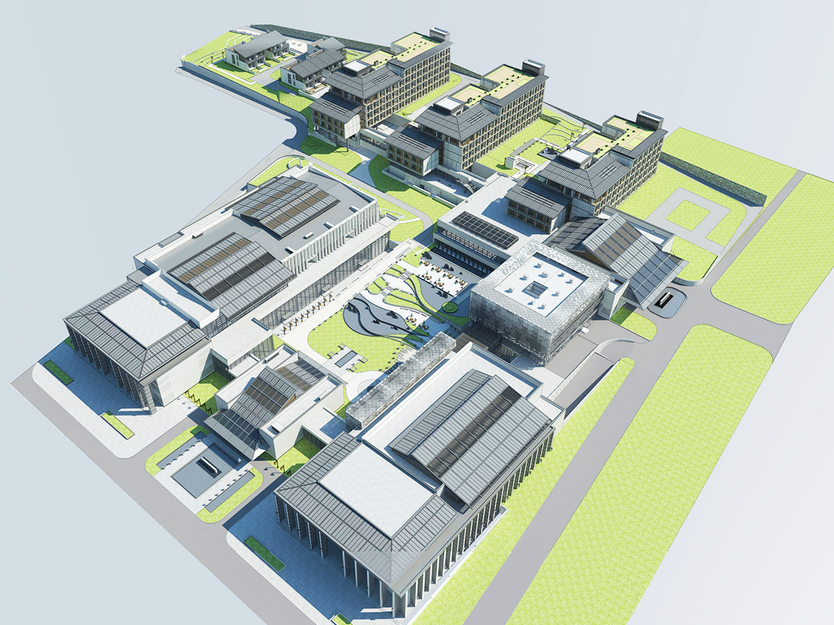
Designing a massive facility requires strict financial evaluation. The raw cost of a clear span structure does not scale linearly. Instead, it scales exponentially as lengths push beyond standard thresholds.
Adding another twenty feet to a 150-foot clear span requires drastically heavier framing. The raw material weight spikes dramatically. Engineering complexity multiplies at this stage. Weld sizes increase. Connection plates grow much thicker to handle the added moment forces.
At a certain point, the pursuit of zero interior columns yields diminishing returns. The extra floor space might not justify the massive structural upgrade. You must carefully weigh the spatial benefits against these exponential price hikes. Savvy developers know exactly when to pivot toward supported center-column designs.
Compare a 150-foot clear span directly against a 150-foot multi-span configuration. A multi-span design utilizes a single interior center column. This effectively creates two continuous 75-foot sections.
The multi-span approach significantly reduces overall material weight. Lighter frames require smaller concrete foundations. This strategy drastically lowers factory fabrication expenses. It also requires much smaller lifting equipment on the job site.
Buyers must evaluate their specific operational workflows. Ask yourself these practical questions:
Does moving large aircraft strictly require zero interior obstructions?
Can your manufacturing assembly line route efficiently around a center pillar?
Will your warehouse storage racks easily integrate between standard column grids?
Moving airplanes absolutely demands wide open space. However, standard warehousing operations often function perfectly around interior columns. Choosing a multi-span layout saves substantial capital when daily workflows allow it.
Project planners frequently overlook a major logistical bottleneck. Standard highway transportation constraints strictly limit prefabricated component sizes. Regular flatbed trucks safely carry items up to roughly 60 or 80 feet.
Once components exceed these standard freight limits, logistics become highly complicated. Moving massive structures requires expensive oversized load permits. You will likely need pilot escort vehicles driving ahead and behind the truck. Transport companies must perform detailed route surveys to avoid low bridges and tight highway curves.
These transportation hurdles quickly inflate project budgets. They can also cause significant delivery delays. If local authorities restrict certain routes due to road construction, your shipment stops entirely. Planners must deeply consider highway rules before finalizing massive structural designs.
Manufacturers engineer multi-piece solutions to solve these complex transportation issues. You will frequently see piggyback designs and spliced configurations in commercial builds.
These modular approaches keep individual pieces within standard shipping dimensions. Manufacturers split a massive 120-foot frame into three manageable 40-foot sections. The trucks deliver the parts safely, quickly, and affordably.
However, this strategy creates a distinct trade-off on the job site. You benefit from lower freight costs but face much higher on-site assembly demands. Field crews must bolt these sections together precisely. This field bolting requires specialized labor. It also significantly increases expensive crane rental time. The crane must hold sections mid-air while workers secure the splice plates. Project managers must calculate both variables to find the most efficient installation solution.
You must clearly define your exact performance requirements before purchasing materials. Structural engineers and manufacturers need absolute minimum data points to proceed safely.
First, they must thoroughly understand your local building codes. Second, you must detail the intended daily facility use. Third, provide the exact roofing material weight, including any future solar panel additions. Finally, supply precise footprint dimensions.
Missing data leads directly to inaccurate load calculations. Always provide comprehensive site details upfront. A well-designed steel truss relies entirely on accurate preliminary data. Guessing environmental loads guarantees future structural failures.
Follow this simple checklist when gathering project data:
Identify the exact physical address to pull accurate wind and snow maps.
List every piece of mechanical equipment hanging from the interior ceiling.
Determine the required interior clearance height for machinery or vehicles.
Specify the exact roofing material, including the final insulation thickness.
Selecting the right manufacturing partner ensures long-term project success. You should look for companies providing highly detailed, site-specific engineering drawings. These plans must carry official stamps from a licensed structural engineer.
Avoid manufacturers relying solely on generic span tables. Generic data cannot account for unique local weather conditions. A generic chart might approve a 100-foot span, but it completely ignores your local hurricane risk.
Emphasize strict compliance with standard industry criteria. For example, cold-formed products must strictly adhere to AISI standard specifications. Verifying industry certifications guarantees structural reliability. It also ensures rapid building code compliance during municipal inspections.
Steel engineering allows modern builders to span distances impossible for traditional timber. However, just because you can build an extreme span does not mean you should. Optimal structural design requires a careful, highly calculated balancing act. You must align material capabilities with local environmental loads. You must weigh logistical transportation constraints against available construction budgets. Pushing past standard limits triggers exponential material weight increases and demands highly specialized fabrication. Moving forward, consult directly with a licensed structural engineer early in the planning phase. Alternatively, partner with a certified pre-engineered building manufacturer. Always demand site-specific load calculations before finalizing your architectural floor plans. Doing so guarantees a safe, structurally optimized, and highly functional facility for years to come.
A: Maximum lengths vary significantly by material type. Standard Cold-Formed Steel (CFS) typically reaches up to 80 feet. Heavy structural steel and rigid Pre-Engineered Building (PEB) systems can achieve clear spans exceeding 300 feet. However, pushing these extreme limits requires highly customized engineering, drastically thicker metal profiles, and exponentially increases overall project budgets.
A: Spacing shares a direct inverse relationship with distance. Wider spacing places heavier structural loads onto each individual frame, which reduces the maximum safe distance it can cross. Conversely, applying tighter spacing distributes the roof weight more evenly. This allows you to achieve longer structural spans using the exact same profile thickness.
A: No, they cannot. Flat or parallel-chord designs completely lack the necessary structural depth found in pitched alternatives. This reduced geometric depth severely limits their clear capacity. Consequently, flat profiles remain much more susceptible to excessive deflection and downward bowing when exposed to heavy environmental loads like deep snow.


